CertExams.com Simulator Lab Exercises Answers
Console Based :
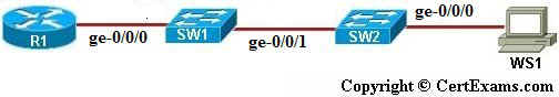
Description: This lab exercise demonstrates trunk concept in VLANs. i.e with trunk set up on only one of the the two switches and see that ping fails from R1 to WS1, correct the configuration by setting up trunk on both the switches and verifying the same.
Instructions:
1. Connect to R1 and configure the IP address of 192.168.1.1/24 on the ge-0/0/0 interface
2. To assign ip address to WS1 click network diagram button and in network diagram window click WS1icon from the diagram. And in WS1 prompt enter 192.168.1.2/24 ip address and default gateway 192.168.1.1.
3. Select device SW1 from network diagram
4. Enter configuration mode of SW1
5. Create a vlan named vlan1 with vlan-id of 100
6. Make the interface ge-0/0/0 member of the vlan1
7. Select device SW2 from network diagram
8. Also create a vlan named vlan1 with vlan-id of 100
9. Make the interface ge-0/0/0 member of vlan1
10. Issue “show vlans” command to view VLANs and its member interfaces on both switches
11. Now ping from WS1 to R1 and see that it fails as there is no trunk line enabled to carry traffic on any VLAN
12. Configure the trunk on ge-0/0/1 port of SW1 and now ping from WS1 to R1 and see that it fails because trunk is to be configured on both the switches to carry traffic.
13. Now configure trunk on ge-0/0/1 port of SW2 and issue appropriate show commands to check the same
14. Ping from WS1 to R1 and see that ping is now successful
GUI Based :
Instructions:
1. Select device R1 from Select device drop down box
2. Click configure button to enable left navigation pane
3. Select Interfaces > Interface Configuration from left navigation pane. Interface Configuration screen appears , select ge-0/0/0 interface from available interface list and click Edit button.
4. Configure Interfaces screen appears enter the ip address as 192.168.1.1 in ip address field and prefix as 24 and click OK button.
5. To assign ip address to WS1 select the device WS1 and click PC IPV4 properties from left pane.
6. In PC IPV4 properties window click option button Use the following address to enable the ip address , mask and default -gateway fields. Enter 192.168.1.2 as ip address , 255.255.255.0 as mask and 192.168.1.1 as default gateway and click OK button.
7. Ping R1 from WS1 and see that ping is successful
8. Select device SW1 and click configure button and create a vlan by name vlan1 and id 100 , to do this select Switching >VLAN from left pane and in Add VLAN window enter vlan1 in Vlan Name field and 100 in vlan id field and click OK button
9. To make the interface ge-0/0/0 of SW1 to the member of created vlan, click Switching >VLAN from left pane ,in Add VLAN window click Ports tab select ge-0/0/0 from interface port drop down and select vlan1 from vlan member drop down and click OK button
10. Select device SW2 and configure the vlan by name vlan1 and id 100 , to do this select Switching> VLAN from left pane and in Add VLAN window enter vlan1 in Vlan Name field and 100 in vlanid field and click OK button
11. To make the interface ge-0/0/0 of SW2 to the member of created vlan ,click Switching >VLAN from left pane ,in Add VLAN window click Ports tab select ge-0/0/0 from interface port drop down, select vlan1 from vlan member drop down and click OK button
12. Now ping R1 from WS1 see that ping fails since there is no trunk line enabled to carry traffic on any vlan
13. Select device SW1 and click configure button and select Switching > VLAN and in Add Vlan window click ports tab and select ge-0/0/1 from interface port drop down and select trunk from port mode drop down and click OK button.
14. Now ping R1 from WS1 see that it fails since trunk is not enabled on switch SW2.
15. Select device SW2 and click configure button and select Switching > VLAN and in Add Vlan window click ports tab and select ge-0/0/1 from interface port drop down and select trunk from port mode drop down and click OK button.
16. Now ping R1 from WS1 and see that it should be successful.
Note: Please refer to the CertExams.com Juniper Network Simulator software for complete lab with GUI Interface.