CertExams.com Simulator Lab Exercises Answers
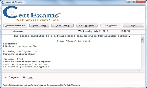
Console Based :
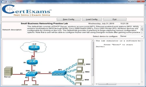
Description: This lab exercise helps to get familiar with the benefits of a VLAN and also in understanding the process to configure a router and a switch to support VLANs.
Instructions:
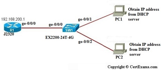
1. Connect to R1 and configure the IP address of 192.168.200.1/24 on the ge-0/0/0 interface
2. Select device SW1 from network diagram and exit
3. Enter into configuration mode of SW1
4. Create vlan by name wrs with vlan id 10
5. Make the interfaces ge-0/0/1 and ge-0/0/2 member of vlan wrs
6. Create layer 3 interface for the created vlan
7. Create DHCP services on the EX switch by creating a DHCP pool for vlan 10
8. Create a virtual interface for the created vlan that l3 interface for vlan 10
9.To assign ip address to PC1 click network diagram button and in network diagram window click PC1 icon from the diagram. Type ip dhcp command on PC1 command prompt.
10. To assign ip address to PC2 click network diagram button and in network diagram window click PC2 icon from the diagram. Type ip dhcp command on PC1 command prompt.
11. Now ping PC1 from PC2 see that ping is successful and try to ping R1 from PC1 and PC2 ping fails(This is because on the switch,VLAN 10 is set to cover only port 1 and port2 that is ge-0/0/1 and ge-0/0/2)
12. Connect to Switch SW1 , assign ge-0/0/0 to VLAN 10 . This would allow to ping all of the devices
13. Issue pings from R1 to PC1 and PC2 and from PC1 and PC2 to R1 and check the connectivity
GUI Based :
Instructions:
1. Select device R1 from Select device drop down box
2. Click configure button to enable left navigation pane
3. Select Interfaces > Interface Configuration from left navigation pane. Interface Configuration screen appears , select ge-0/0/0 interface from available interface list and click Edit button.
4. Configure Interfaces screen appears enter the ip address as 192.168.200.1 in ip address field and prefix as 24 and click OK button.
5. Select device SW1 create a vlan by name wrs with vlan id 10 by selecting Switching > VLAN from left pane and in Add vlan window enter wrs as vlan name and 10 as vlan id and click Add button
6. To assign ge-0/0/1 and ge-0/0/2 interface to member of the created vlan again click Switching > VLAN from left pane , in Add VLAN window click Ports tab select ge-0/0/1 from interface port drop down and select wrs from vlan member drop down and click OK button
7. Repeat step 6 to assign ge-0//0/2 interface to the member of vlan 10.
8. To create layer 3 interface and assign ip address to vlan interface 10 , click Switching > Vlan from left pane and in Add Vlan window click IP address tab and select 10 from Vlan unit drop down and enter 192.168.200.2 as ip address and 24 as prefix and click OK button.
9. To associate l3 interface for vlan 10 ,again click Switching > VLAN from left pane and in Add vlan window click IP address tab and in l3-interface Configuration select 10 from vlan unit drop down and wrs from vlan member drop down and click OK button.
10. To configure SW1 as DHCP server select Services > DHCP Server from left navigation pane
11. DHCP Pool information window appears click Add button.
12. In DHCP Pool and Server configuration window enter DHCP subnet as 192.168.200.0/24 , low address range as 192.168.200.3 and high address range as 192.168.200.254 default lease time 23456, server identifier 192.168.200.3 ,Domain Name wrs.com , DNS name server 192.168.200.3 , Gateway router 192.168.200.3 and click OK button.
13. To obtain IP address to PC1 via DHCP server select device PC1 and select PC IPV4 properties from left navigation pane , PC IPV4 properties window appears select option button obtain IP address automatically (if it was not selected) and click OK button
14. To obtain IP address to PC2 select the device PC2 and follow step 10.
15. Now ping PC1 from PC2 see that ping is successful and try to ping R1 from PC1 and PC2 ping fails(This is because on the switch,VLAN 10 is set to cover only port 1 and port2 that is ge-0/0/1 and ge-0/0/2) that is click troubleshoot button and select ping host from left pane enter R1 in ping/traceroute field and click OK button.
16. Select device SW1and click configure button and to assign ge-0/0/0 to VLAN 10 ,Click Switching >VLAN from left pane ,in Add VLAN window click Ports tab select ge-0/0/0 from interface port drop down and select wrs from vlan member drop down and click OK button. This would allow to ping all of the devices
17. Issue pings from R1 to PC1 and PC2 and from PC1 and PC2 to R1 and check the connectivity
Note: Please refer to the CertExams.com Juniper Network Simulator software for complete lab with GUI Interface.