Help Contents | Back | Next | Simulator Home
1. Network designer is used to design any simple router Network. The network diagram can be exported and then used by the simulator module to configure according to the requirement.
The supported devices and the connectors include the following:
The Supported Connectors are:
2. The network designer is initiated by selecting Network Designer -> Open Network Designer as shown in the figure below:
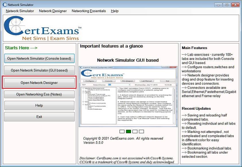
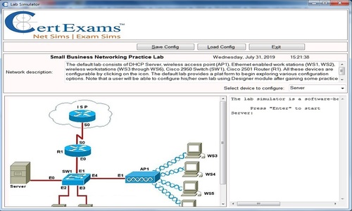
Figure below shows the Main Screen of the Designer:
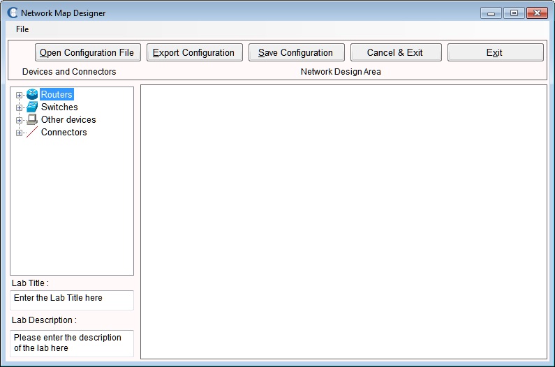
3. The network designer has four important sections. These are "Devices and Connectors" section, "Lab Description" section, "Lab Title", and the "Network Design Area" section. Each of these sections are described subsequently.
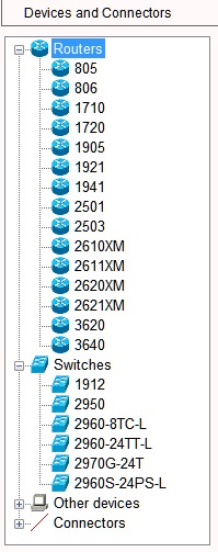
1. Devices and connections: This section is further divided into several sections like Routers, Switches, Other Devices, and Connectors. You will find types of entities supported by the network designer here. Expand the + sign to view the supported items under a given category.
2. Lab Description: Network description area is simply a space to
enter any desired text. It may include network description or a problem description
that needs to be fixed.
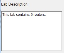
3. Lab Title : This area can be used to give any title to the Network Lab you are designing according to your convenience.
4. Network Design area: The design area is to the right of the screen. This is the place used for designing a network diagram.
4. Working with the Designer:
1. Dragging and dropping devices and connections: To include a device in the network, simply click and drag the device into the work area. Release the mouse after placing the device in the desired position. On dropping the device you will be prompted to enter a Hostname of the device. By default there will a Hostname typed in the input text area. If you want a different Hostname then clear it and enter the hostname that you want to assign for that device. You will also be asked to provide the ip address information for the interfaces present. You may assign the ip address and subnet information now or at a later time. It is optional. Similarly, to connect two existing devices, drag appropriate connector into the work area. Take the mouse onto the first device to which the connection is to be provided. Drag the other end onto the device where the connection needs to be terminated. During the process, you will be asked to provide the device interface type and number (example S0, E0 etc.) for each end of the connection.
2. How to configure a device: On right mouse clicking a device,
you get several options as shown in the figure.
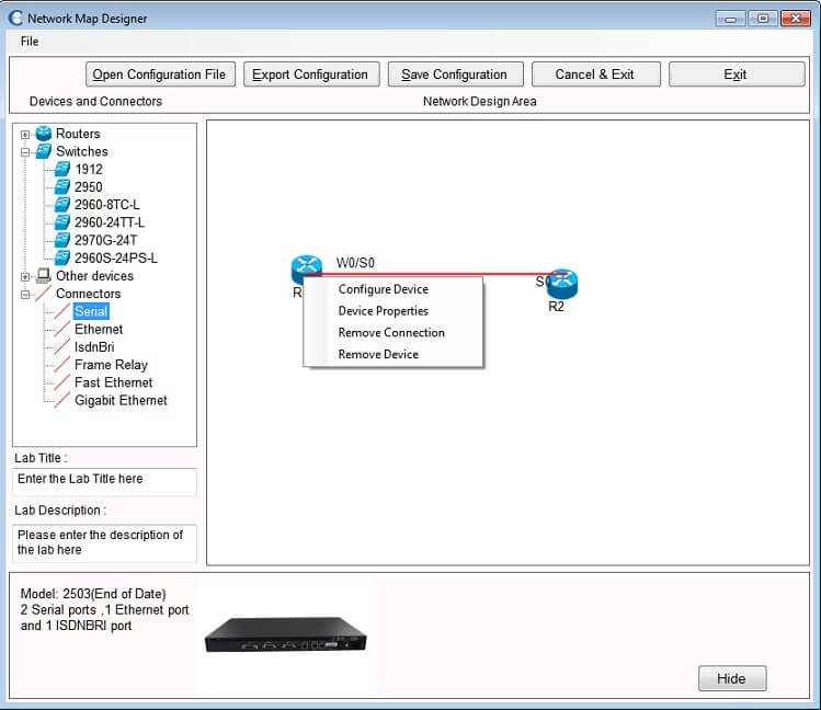
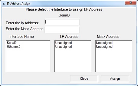
Selecting "Configure Device" will lead to graphical interface configuration menu. Here, you select the interface and enter corresponding ip address and subnet mask. You can also exit without assigning and ip addresses. Please note that the interface configuration can also be done in the network simulator section of the program.
To establish a Connection between the two Devices, select the type of Connection from available Connectors, drag and drop it on a device which has to be connected. On doing so you will be prompted for the Interface to select for this Connection. Select the interface and and click on Close button. Now the mouse point to the other end of the connection. Drop the other end of the Connector on the other device.
3. Display a device configuration data: Selecting device properties displays the current interface configuration details for the selected device with respect to connected devices. A screen shot is shown below. It also shows unconnected interfaces on a device.

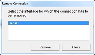
4. Remove a connection: As shown in the screen-shot, you can select the interface that needs to be released of any connections. This screen shows only the connected interface on a selected device. Select the Interface and click on "Remove" to remove that Connection.
5. Remove a device:
By choosing this option, you can permanently
remove a device and associated connections from the network designer.