CertExams.com Simulator Lab Exercises Answers
Console Based :
Description : This is a basic lab exercise on frame-relay which showcases on frame-relay connection and show commands associated to frame-relay.
Instructions:
1. Configure Frame-Relay on R1 Serial 0/0 interface to an IP Address of 192.168.100.1 255.255.255.0 and enable the interface. Use frame-relay map statements for static mapping and use ANSI as its LMI type
2. Configure Frame-Relay on R2 Serial 0/0 interface to an IP Address of 192.168.100.2 255.255.255.0 and enable the interface. Use frame-relay map statements for static mapping and use ANSI as its LMI type
3. Use show interfaces serial 0/0 command on R1 and R2 in order to check that the routers are successfully connected to their frame-relay network. See that in the output, the encapsulation type is Frame-Relay
4. Issue show frame-relay map command on R1 and R2 which displays the mappings of local DLCIs to remote IP Addresses
5. Issue show frame-relay lmi command on R1 which displays the Local Management Interface statistics
6. Issue show frame-relay pvc <dlci-num> command on R1 and R2 which displays the permanent virtual circuit (PVC) mappings for the router.
7. Ping from R2 to R1 and check connectivity
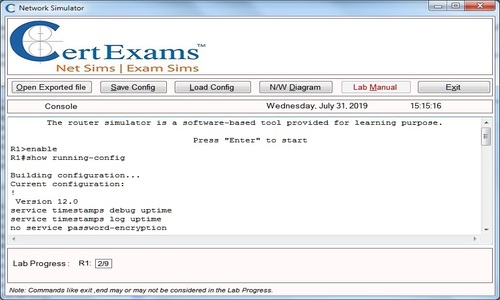
Note: Please refer to the CertExams.com Network Simulator software for complete lab with commands.
GUI Based :
Instructions:
1. Configure Frame-Relay on R1 Serial 0/0 interface and enable the interface using Configure > Interface and Connections and select Serial 0/0 interface and click Create New Connection button. In Serial 0/0 interface wizard select encapsulation as Frame-relay and IP address as 192.168.100.1 255.255.255.0 and enable the interface using Edit Interface Connections select S0/0 interface and click Edit button. In interface feature Edit dialog select “Enable” Interface Status drop down box and click OK button.
2. Click Router > Frame-Relay Configuration. Frame Relay Configuration settings screen appears select S0/0 interface from Select Interface type drop down box.
3. Enter the Frame-Relay map ip address as 192.168.100.2 and dlci number 105 and select LMI type as ansi from LMI type drop down box.
4. Repeat step 1 -3 for router R2 with ip address 192.168.100.2 255.255.255.0 and frame-relay static mapping with map ip as 192.168.100.1, dlci number as 501 and lmi type “ansi”
5. Use “show interfaces serial 0/0” command on R1 and R2 in order to check that the routers are successfully connected to their frame-relay network. See that in the output, the encapsulation type is Frame-Relay
6. Issue “show frame-relay map” command on R1 and R2 which displays the mappings of local DLCIs to remote IP Addresses.
7. Issue “show frame-relay lmi” command on R1 and R2 which displays the Local Management Interface statistics
8. Issue “show frame-relay pvc <dlci-num> command on R1 and R2 which displays the permanent virtual circuit (PVC) mappings for the router with R1 dlci number 105 and R2 with dlci number 501.
9. Ping from R2 to R1(192.168.100.1) and check connectivity using Utilities>Ping and Traceroute.
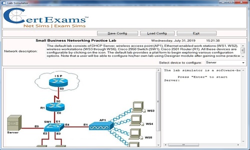
Note: Please refer to the CertExams.com Network Simulator software for complete lab with GUI Interface.