CertExams.com Simulator Lab Exercises Answers
Console Based :
Description: In OSPF single area, you configure OSPF network with an area ID.The configuration example uses four routers working in area 200.
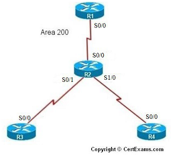
IP Address Assignment Table
| R1-s0/0 | 192.168.1.1 | 255.255.255.0 |
| R2-s0/0 | 192.168.1.2 |
255.255.255.0 |
| R2-s0/1 | 192.168.2.1 | 255.255.255.0 |
| R2-s1/0 | 192.168.3.1 | 255.255.255.0 |
| R3-s0/0 | 192.168.2.2 | 255.255.255.0 |
| R4-s0/0 | 192.168.3.2 | 255.255.255.0 |
Instructions:
1. Assign IP Addresses on all the devices as per the above table and bring all the interfaces to up state
2. On R1 enable OSPF routing with process 1 and area as 200 for the network 192.168.1.0
3. On R2 enable OSPF routing with process 1 and area as 200 for the network 192.168.2.0 and 192.168.3.0
4. On R3 enable OSPF routing with process 1 and area as 200 for the network 192.168.2.0
5. On R4 enable OSPF routing with process 1 and area as 200 for the network 192.168.3.0
6. Ping R1 from R4, you will see ping failure
7. Ping R2 from R4, you will see ping success (This implies connectivity failure from R2 to R1)
8. Issue command on R2 to see OSPF database
9. You will see that there is no link state entry for network 192.168.1.0, so enable OSPF routing on R2 for this network.
10. Ping R1 from R4, you will see ping success
Note : You need to assign the IP addresses and make the interfaces up (by issuing no shutdown
commands at appropriate interfaces) for all the devices before proceeding with the
commands/
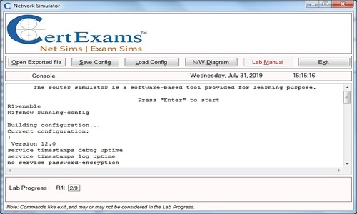
Note: Please refer to the CertExams.com Network Simulator software for complete lab with commands.
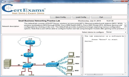
GUI Based :
Instructions:
1. Select R1 from Select Device drop down box.
2. Choose configure > Interface Management > Interface and Connections.
3. In Edit Interface connections tab select the S0/0 interface and click edit button
4. Configure the IP address as 192.168.1.1 255.255.255.0 and enable the interface status.
5. To enable OSPF routing on R1 , choose Router > Dynamic Routing , select OSPF from the protocol list and click Edit button.
6. In the Edit IP dynamic routing window enter OSPF process id 1 and click add button to add a network.
7. Enter 192.168.1.0 as network address , wildcard mask 0.0.0.255 and area 200 and click OK button.
8. Select device R2 from Select Device drop down box.
9. Repeat steps 2 – 4 for configuring R2's S0/0 interface ip address as 192.168.1.2 255.255.255.0 , S0/1 interface ip address as 192.168.2.1 255.255.255.0 and S1/0 interface ip address as 192.168.3.1 255.255.255.0
10. To enable OSPF routing on R2 , choose Router > Dynamic Routing , select OSPF from the protocol list and click Edit button.
11. In the Edit IP dynamic routing window enter OSPF process id 1 and click add button to add a network.
12. Enter 192.168.2.0 as network address , wildcard mask 0.0.0.255 and area 200 and click OK button.
13. Click add button again in Edit IP dynamic routing window and enter 192.168.3.0 as network address , wildcard mask as 0.0.0.255 and area 200
14. Select R3 from Select Device drop down box.
15. Repeat steps 2 – 7 for configuring R3 S0/0 interface ip address as 192.168.2.2 255.255.255.0 and network addresses 192.168.2.0 and wildcard mask as 0.0.0.255 and area 200
16. Select R4 from Select Device drop down box.
17. Repeat steps 2 – 7 for configuring R4 S0/0 interface ip address as 192.168.3.2 255.255.255.0 and network addresses 192.168.3.0 and wildcard mask as 0.0.0.255 area 200
18. Ping R1 from R4, you will see ping failure
19. Ping R2 from R4, you will see ping success (This implies connectivity failure from R2 to R1)
20. Issue “show ip ospf database” command on R2 using View > IOS show commands.
21. You will see that there is no link state for network 192.168.1.0 , so enable OSPF routing on R2 for this network. Follow steps 5 -7 for assigning network address .
22. Choose Router > Dynamic Routing select OSPF from the protocol list and click Edit button.
23. In the Edit IP dynamic routing window enter OSPF process id 1 and click add button to add a network 192.168.1.0 , wildcard mask 0.0.0.255 and area 200.
24. Now ping R1 from R4 you will see that it is successful
Note : You need to assign the IP addresses and make the interfaces up (by issuing no shutdown
commands at appropriate interfaces) for all the devices before proceeding with the following
commands