CertExams.com Simulator Lab Exercises Answers
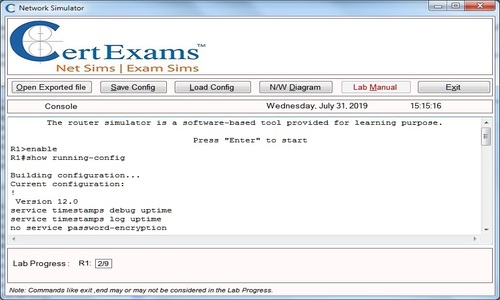
Console Based :
Description : This lab exercise demonstrates the concept of Extended Access List by configuring and verifying the same.
Instructions:
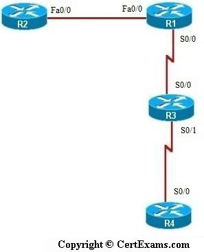
1. Connect to R1 and set the IP Address on fa 0/0 interface to 192.168.1.1/24 and the Serial 0/0 interface to 192.168.2.1/24 and enable the interfaces. Enable Routing Protocol RIP on R1 and add the network to Fa0/0 and Serial 0/0 interfaces
2. Connect to R2 and set the IP Address on Fa0/0 interface to 192.168.1.2/24, enable the interface and enable RIP on R2, add the network to Fa0/0 interface
3. Connect to R3 and set the IP Address on Serial 0/0 interface to 192.168.2.2/24 and Serial 0/1 interface to 192.168.3.1/24 and enable the interfaces. Enable RIP protocol on R3 and add the network to Serial 0/0 and Serial 0/1 interfaces
4. Connect to R4 and set the IP Address on Serial 0/0 interface to 192.168.3.2/24, enable the interface and enable RIP on R3, add the network to Serial 0/0 interface
5. Ping R2 from both R3 and R4 and see that it is successful
6. Configure Extended Access-List 101 on R1 that allows telnet traffic from R3 (192.168.2.2) and allow icmp traffic from R4 (192.168.3.2) and block all other traffic
7. Apply this access-list to R1’s Serial 0/0 interface on inbound traffic and check the same using “show ip interface” command
8. Verify the Extended Access List applied on R1 by pinging and telneting R2 from R3 and
R4(R3 (192.168.2.2)) should not be able to ping R2 but should be able to telnet to R2 and
R4 (192.168.3.2) should be able to ping R2 but not telnet to it)
Note: Please refer to the CertExams.com Network Simulator software for complete lab with commands.
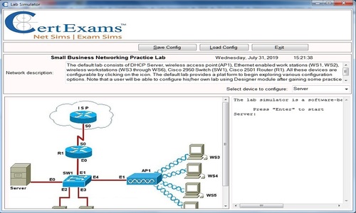
GUI Based :
Description: This lab exercise demonstrates the concept of Extended Access List by configuring and verifying the same
Instructions:
1. Configure IP address of all the device as per the above table
2. Configure Extended Access-List 101 on R1 that allows telnet traffic from R3 (192.168.2.2)
and allow icmp traffic from R4 (192.168.3.2) and block all other traffic.
3. In Add a Rule window enter access list number as 101 and select as Extended Rule from
Type drop down and click Add button.
4. In add an Extended Rule entry window select action as permit and select tcp from Protocol and
Service.
5. In source Host/Network select host from type drop down box and enter the IP address as
192.168.2.2 and in destination Host/Network select Any IP address and select Destination Port “=”
and telnet.
6. To apply another access-list with number 101 click Add button in Add a Rule window.
7. In extended Access-List entry screen select permit from select an action drop down box .
8. Select host from Source Host/Network enter 192.168.3.2 in IP address field.
9. Select Any IP address from Destination Host/Network.
10. Select icmp from protocol and service and click OK button
11. In add a rule window click associate and select interface as s0 and direction as inbound
from Associate with an Interface screen and click OK button.
12. On R1 issue show ip interface command using View > IOS show command.
Note: Please refer to the CertExams.com Network Simulator software for complete lab with GUI Interface.