CertExams.com Simulator Lab Exercises Answers
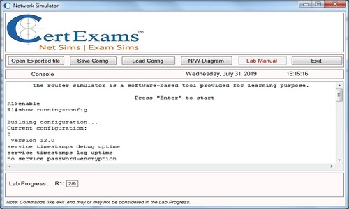
Console Based :
Description : This lab exercise demonstrates configuring and implementing Extended Access-Lists.
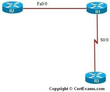
IP Address Assignment Table
| Device | Interface | IP Address | Mask |
| R1 | Fa0/0 S0/0 |
192.168.200.1 |
255.255.255.240 255.255.255.240 |
| R2 | Fa0/0 | 192.168.200.2 | 255.255.255.240 |
| R3 | S0/0 | 192.168.200.18 | 255.255.255.240 |
Instructions:
1. Connect to R1 and set the IP Address of FastEthernet and Serial interfaces as given in the table and enable the interfaces
2. To facilitate communication between R2 and R3, enable RIP Routing Protocol on R1 and add the network for Fa0/0 and serial 0/0 interfaces
3. Connect to R2 and set the IP Address of Fastethernet interface as given in the table and enable the interface
4. On R2, enable RIP and add the network for fa0/0
5. From R2, ping R1’s fa0/0 interface to ensure that the connection exists
6. Connect to R3 and set the IP Address of Serial interface as given in the table and enable the interface and ping R1’s Serial 0/0 interface
7. Also verify that you can ping R2’s fa0/0 interface from R3
8. Enter into global configuration mode of R1
9. Now create Extended Access List that accomplishes two things.
i. Allow only telnet traffic from the subnet off of R1’s Serial 0/0 interface to come into R1.
ii. Next, allow any traffic from R1’s fa0/0 subnet to travel anywhere
10. Create access list 101 to allow only telnet traffic from the 192.168.200.16 subnet. Use the keyword log to display output to the router every time this line on the access list is invoked.
11. Create access list 102 to permit all traffic from 192.168.200.0 subnet and use the keyword log.
12. To apply these access lists on the interfaces, enter into interface configuration mode for
Serial 0/0 interface of R1 and apply access list 101 inbound and 101 outbound and access
list 102 inbound for fa0/0 interface
Note: Please refer to the CertExams.com Network Simulator software for complete lab with commands.
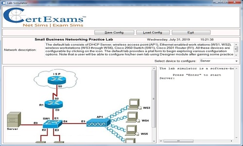
GUI Based :
Instructions:
1. Configure the ip address of all the devices as per the table.
2. To facilitate communication between R2 and R3, enable RIP Routing Protocol on R1 and add the network for Fa0/0 and serial 0/0 interfaces using Router > Dynamic routing and select RIP protocol and click Edit button. Edit IP Dynamic Routing window appears click Add button to add a network 192.168.200.0 ,192.168.200.16
3. Repeat the step 2 for configuring router R2 with network address 192.168.200.0 and R3 with network address 192.168.200.16
4. Now create Extended Access List that accomplishes two things.
i. Allow only telnet traffic from the subnet off of R1’s Serial 0 interface to come into R1.
ii. Next, allow any traffic from R1’s fa0/0 0 subnet to travel anywhere
5. Create access list 101 to allow only telnet traffic from the 192.168.200.16 subnet. Using Router > ACL > ACL Editor > click Add button.
6. Set Access-List number 101 and select Extended Rule from Type drop down box and click Add
7. In Add an Extended Rule Entry select “permit” from select an action drop down box.
8. Select “A Network” from Source Host/Network and type 192.168.200.16 in IP address field and 0.0.0.15 in wildcard mask field.
9. Select “Any IP address” from Destination Host/Network. Select “tcp” from Protocol and Service options. Select Destination Port “=” and telnet and click OK button.
10. To apply access list 102 in Add a Rule window change the access list number 102 in Name/Number field. Select Extended Rule from Type drop down box and click Add button.
11. In Add an Extended Rule Entry “permit” from select an action drop down box.
12. Select “A Network” from Source Host/Network and type 192.168.200.0 in IP address field and 0.0.0.15 in wildcard mask field.
13. Select “Any IP address” from Destination Host/Network. Select “ip” from Protocol and Service options and click OK button.
14. In Add a Rule window click Associate button.
15. Associate with an interface screen appears select S0/0 interface and direction as “inbound” and click OK button.
16. Click Associate button again and in Associate with an interface screen select S0/0 interface and direction as “outbound” and click OK button.
17. In add a Rule screen change access-list number 102 and click associate button.
18. In Associate with an interface screen select Fa0/0 interface and direction as “inbound” and click OK button.
19. View access list applied on R1 using “show access-list” command using View > IOS Show commands
20. Verify the access-list applied using Utilities > Ping and Traceroute , select device R2 and ping the ip address 192.168.200.1
21. Select device R3 and ping 192.168.200.17 and 192.168.200.2 and verify the connectivity
Note: Please refer to the CertExams.com Network Simulator software for complete lab with GUI Interface.