CertExams.com Simulator Lab Exercises Answers
Console Based :
Description : This lab exercise demonstrates creating Named Access Lists
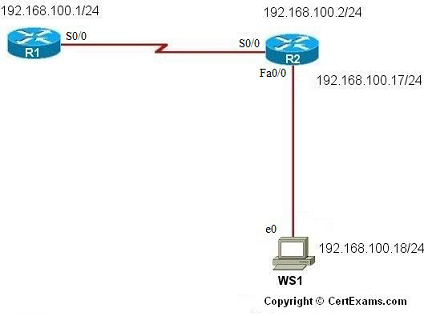
IP Address Assignment Table
| Device | Interface | IP Address/Mask |
| R1 | S0/0 | 192.168.100.1/24 |
| R2 | Fa0/0 S0/0 |
192.168.100.17/24 192.168.100.2/24 |
| Device | IP Address/Mask | Default-Gateway |
| WS1 | 192.168.100.18/24 |
192.168.100.17 |
Instructions:
1. Configure the routers R1, R2 and workstation WS1 as per the table given above.
2. Configure RIP on the routers with proper network statements
3. Issue show ip route command to make sure that the routes have been received on each router
4. Verify ping to R1 from WS1
5. Create an access list that prevents ping traffic originating from WS1 and destined for R1 from reaching R1
6. Extended access list is created and the statement deny icmp host 192.168.100.18 192.168.100.1 0.0.0.0 log denies any ICMP traffic with a source IP Address of 192.168.100.18 that is destined for 192.168.100.1, the wild card mask of 0.0.0.0, i.e the IP Address must match exactly
7. Next, apply the access list to inbound traffic on the Serial 0/0 interface of R1
8. Try pinging R1 from WS1 and R1 from R2
9. Connect to R1 again, two separate log messages must be seen here. The first one is
denying the ping from WS1 and second which is allowing the ping from R2
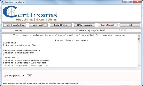
Note: Please refer to the CertExams.com Network Simulator software for complete lab with commands.
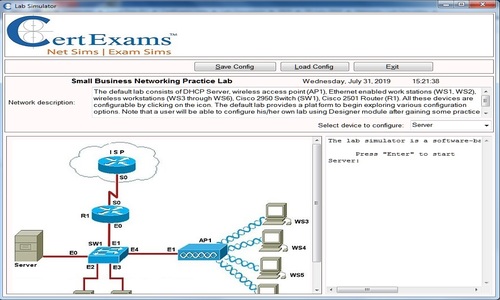
GUI Based :
Instructions:
1. Select device R1 from Select device drop down box.
2. Click Configure button, this enables left navigation pane.
3. In left navigation pane click Interface Management > Interface and Connection.
4. In Interface and Connection screen click Edit Interface Connection tab.
5. From the interface list select S0/0 interface and click Edit button.
6. In Edit interface feature dialog screen enter the IP Address as 192.168.100.1 and mask address 255.255.255.0 ,Select Enable from Interface Status drop down box and click OK button.
7. Click Router > Dynamic Routing from left navigation pane. This opens up Routing screen. Select RIP from Dynamic Routing list and click Edit button.
8. In Edit IP Dynamic Routing screen select RIP version 2 and click ADD button.
9. Enter the network address as 192.168.100.0 in Add a Network window and click OK button.
10. Select Device R2 from Select Device drop down box.
11. Repeat steps 3 – 9 for configuring R2's Fa0/0 interface ip address as 192.168.100.17 255.255.255.0 and S0/0 interface ip address as 192.168.100.2 255.255.255.0 and network address 192.168.100.0
12. Select WS1 from Select Device drop down box.
13. Repeat the steps 3 -6 for configuring WS1 with IP address as 192.168.100.18 255.255.255.0 and default-gateway ip address as 192.168.100.17.
14. Select R1 from Select Device drop down box.
15. Click Router > ACL > ACL Editor from left navigation pane.
16. Click Add button in Additional Tasks screen
17. In Add a Rule screen enter “denyping” in Name/Number field.
18. Select “Named ACL rule” from Type drop down box and click Add button.
19. In Add Named Access-List entry screen select “deny” from Select an action drop down box.
20. In Source Host/Network select “host” from type drop down box and enter 192.168.100.18 in IP Address field.
21. In Destination Host/Network select “A Network” from type drop down box.
22. Enter IP address 192.168.100.1 and wild card mask as 0.0.0.0
23. Select option button “icmp” from protocol and service options and click OK button.
24. In Add a Rule screen click Add button again. This opens Add Named Access-List entry screen.
25. Select “permit” from Select an action drop down box.
26. In Source Host/Network select “Any IP Address” from type drop down box
27. In Destination Host/Network select “Any IP Address” from type drop down box
28. Select option button “ip” from protocol and service options and click OK button.
29. In add a rule window click associate and select interface as s0/0 and direction as “inbound” from Associate with an interface screen and click OK button.
30. Try pinging R1 from WS1 using Utilities > Ping and Traceroute enter destination ip address as 192.168.100.1
31. Ping R1 from R2 with destination ip address as 192.168.100.1
Note: Please refer to the CertExams.com Network Simulator software for complete lab with GUI Interface.