CertExams.com Simulator Lab Exercises Answers
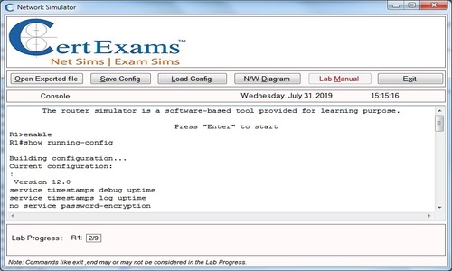
Console Based :
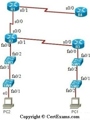
Description: Configure frame-relay using sub-interfaces. Test for connectivity.
Instructions:
1. Assign IP Addresses on all the devices as per the above diagram (On R1 and R4 sub-interface #1 is used)
2. Set the encapsulation parameters appropriately on R1 and R4
3. Ping from PC1 to PC2 and vice versa
Note: Please refer to the CertExams.com Network Simulator software for complete lab with commands.
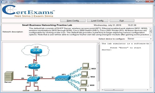
GUI Based :
Instructions:
1. Assign IP address of S0/0 interface of R1 as 175.10.1.1 255.255.255.0. Use Configure > Interface Management > Interface and Connection > select Edit Interface Connection tab > select s0/0 interface and click Edit button. In interface feature edit dialog specify ip address and enable interface status and click OK button.
2. Click Interface Management > Interface and Connection > In Create Connection tab select serial 0/1.1 interface and click Create New Connection button. This opens serial 1.1 interface wizard click next > next > select frame-relay encapsulation and click next. In IP address window specify s0/1.1 interface ip address as 215.10.1.1 255.255.255.0 and click next > next > finish > OK button.
3. Enable s0/1.1 interface using Interface Management > Interface and Connection > click edit interface connection > select s0/1.1 interface and click Edit button. In interface feature edit dialog select “Enable” from Interface Status drop down box and click OK button.
4. Click Router > Dynamic Routing. In Routing window select RIP and click Edit button. In Edit IP Dynamic Routing click Add button. Specify 175.10.1.0 as network number in Add a Network window and click OK button. In Edit IP dynamic Routing window click Add button again and Specify network number as 215.10.1.0 in Add a Network window and click OK button.
5. Select R2 from select device drop down box. Click Interface Management > Interface and Connection > select Edit Interface Connection tab > select s0/0 interface and click Edit button. Specify ip address as 175.10.1.2 255.255.255.0 and Enable the interface status and click OK button.
6. Repeat step 5 for s0/1 and fa0/0 interface of R2 with ip address 180.10.1.1 and 197.10.1.1 respectively.
7. Enable RIP routing on R2 with network number 175.10.1.0, 180.10.1.0 and 197.10.1.0 follow step 4.
8. Select R3 from select device drop down box follow step 5 and specify s0/0 interface ip address as 180.10.1.2 and fa0/0 interface ip address as 195.10.1.1.
9. Enable RIP routing on R3 with network number 180.10.1.0 and 195.10.1.0. Follow step 4.
10. Select R4 from select device drop down box.
11. Click Interface Management > Interface and Connection > In Create Connection tab select serial 0/0.1 interface and click Create New Connection button. This opens serial 0/0.1 interface wizard click next > next > select frame-relay encapsulation and click next. In IP address window specify interface ip address as 215.10.1.2 255.255.255.0 and click next > next > finish > OK button.
12. Enable s 0/0.1 interface using Interface Management > Interface and Connection > click edit interface connection > select s0/0.1 interface and click Edit button. In interface feature edit dialog select “Enable” from Interface Status drop down box and click OK button.
13. Enable RIP routing on R4 with network number 215.10.1.0. follow step 4.
14. Select PC1 from select device drop-down box .
15. Follow step 5 to assign the ip address of e0 interface of PC1 as 195.10.1.2 , mask address 255.255.255.0
16. Follow step 14 and 15 to assign the ip address to PC2 as 197.10.1.2 , mask address as 255.255.255.0
17. Ping from PC1 to PC2 and vice versa using Utilities > Ping and traceroute and enter destination ip address.
Note: Please refer to the CertExams.com Network Simulator software for complete lab with GUI Interface.