CertExams.com Simulator Lab Exercises Answers
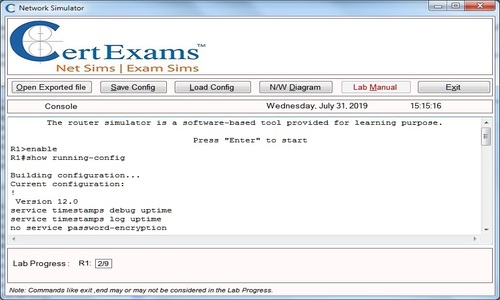
Console Based :
Description : This lab exercise demonstrates the concept of Standard Access List by configuring and verifying the same.
Instructions:
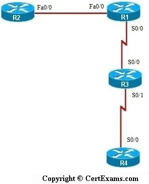
1. Connect to R1 and set the IP Address on fa0/0 interface to 192.168.1.1/24 and the Serial 0/0 interface to 192.168.2.1/24 and enable the interfaces. Enable Routing Protocol RIP on R1 and add the network to Fa0/0 0 and Serial 0/0 interfaces
2. Connect to R2 and set the IP Address on Fa0/0 interface to 192.168.1.2/24, enable the interface and enable RIP on R2, add the network to Fa0/0 interface
3. Connect to R3 and set the IP Address on Serial 0/0 interface to 192.168.2.2/24 and Serial 1 interface to 192.168.3.1/24 and enable the interfaces. Enable RIP protocol on R3 and add the network to Serial 0 and Serial 1 interfaces
4. Connect to R4 and set the IP Address on Serial 0/0 interface to 192.168.3.2/24, enable the interface and enable RIP on R3, add the network to Serial 0/0 interface
5. Ping R2 from both R3 and R4 and see that it is successful
6. Configure a Standard Access-List on R1 that permits traffic from subnet 192.168.2.0 but blocks traffic from all other devices.
7. Next, apply this access-list to R1’s Serial 0/0 interface for inbound traffic
8. Verify the access list that is applied on R1 by issuing ping statements i.e, ping R2 from R3 and R4 and check that ping from R3 in subnet 192.168.2.0 is successful whereas ping from R4 in subnet 192.168.3.0 is not successful
9. Now connect to R1 and issue “show access-list” command which displays the accesslists that are applied on R1
10. Now , try out different cases of applying standard access list and test the same as given
below. But before that remove the previously configured Access Lists on R1 by issuing "no
ip access group 1 in" command on R1 serial 0/0 interface and "no access-list 1" command
on R1 in global configuration mode.
Note: Please refer to the CertExams.com Network Simulator software for complete lab with commands.
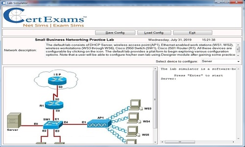
GUI Based :
Description: This lab exercise demonstrates the concept of Standard Access List by configuring and
verifying the same.
Instructions:
1. Configure IP address of all the device as per the above table. Using Interface Management >
Interface and Connections > Edit Interface Connections select the interface and click Edit button. In the
interface feature edit dialog enter the ip address, mask and enable the interface and also enable RIP
routing on R1,R2,R3 and R4.
2. Ping R2 from both R3 and R4 and see that it is successful.
3. Configure a Standard Access-List on R1 that permits traffic from subnet 192.168.2.0 but blocks
traffic from all other devices. Select Router > ACL > ACL Editor and click Add button.
4. Specify access list number 1 and type as standard rule and click add button.
5. In add a standard Rule entry select action permit and In source Host/Network select A network from
Type drop down box and set the ip address as 192.168.2.0 and wildcard mask as 0.0.0.255.
6. Click Associate in Add a Rule screen . Select the interface s0 and direction inbound in Associate withan
Interface screen and click OK button.
7. Verify the access list that is applied on R1 by issuing ping statements i.e, ping R2 from R3 and R4
and check that ping from R3 in subnet 192.168.2.0 is successful whereas ping from R4 in subnet
192.168.3.0 is not successful
8. Now connect to R1 and issue show access-list command which displays the access-lists that are
applied on R1
9. Now , try out different cases of applying standard access list and test the same as given below. But
before that remove the previously configured Access Lists on R1 by clicking delete button. In Add a
Rule Screen. Select the Access-List entry from Rule entry list and click delete button. Repeat the same
step for deleting required number of entries in the list.
10. To configure with different cases follow steps 3-5
Note: Please refer to the CertExams.com Network Simulator software for complete lab with GUI Interface.